Understanding Network Hardware
How Data Travels from the Internet to Your Screen
When you go to a web site, watch a video, or send an email, your data goes through a series of interconnected pieces of equipment, known collectively as devices. Each device performs a function, and knowing how this physical connection works will make better software engineers who are developing broadband systems that rely upon consistent, safe, and growable networks.
Typically, software engineers will work with abstractions of the physical elements of the network stack (examples being: HTTP, TCP/IP, REST API, etc.) without actually knowing the physical element that supports the abstraction. Understanding the physical hardware element will be crucial for when an engineer deploys the application code they have been developing, troubleshooting application issues, and designing growable networks.
Let's follow the physical path your data has taken from the global level (the internet) to your local (your computer) before examining how these same principles work on a larger scale to produce outcomes on a global scale.
How the Internet Reaches You
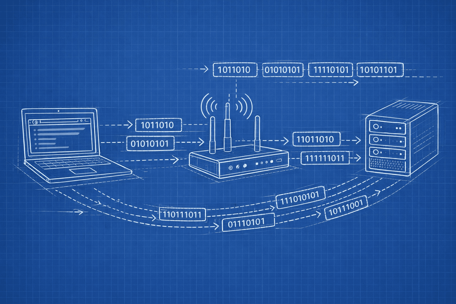
View the Internet as a massive ocean, and your PC as a house that needs an adequate supply of water. To move data from the big ocean to your house, you will have to build a structured framework of pipes and valves to move that data. Network hardware is the backbone of this system by providing the physical pathways (cables), controllers of data flow (routers) and filters for security (firewalls) to deliver data from its source in the ocean to your computer screen.

This is the foundational flow that the internet connection follows. Let’s understand every component in the flow.
The Modem: Your Gateway to the Internet
The ISP (Internet Service Provider) delivers internet using signals through fibers or cables that the computer is unable to understand. As the name ‘Modem’ suggest: Modulator Demodulator, it converts between these analog or specialized digital signals and the standard digital Ethernet packets the network devices expect.
How It Works:
Incoming: The modem receives signals from your ISP and demodulates them into digital data packets
Outgoing: It takes digital packets from your network and modulates them into the signal format your ISP expects
IP Assignment: Your ISP assigns your modem a public IP address—this is your network's identity on the internet
When you deploy applications, your production servers connect through modems (or their datacenter equivalents) to the internet backbone. Understanding this helps you debug connectivity issues and comprehend network boundaries.
Router: The Traffic Director
The modem has only one public IP address, but multiple devices are able to connect to the internet. The router creates a private local network behind the public IP address and routes the packets between the internet and the correct device.
Key functions:
NAT: Provides the public IP (modem’s IP) to all devices connected to the modem.
DHCP Server: Automatically assigns private IP addresses to all devices connected to it (example: 192.168.x.x)
Routing: Routes the packets of data from your network to the internet (and vice versa).
Basic firewall: Often includes simple packet filtering
How It Works:
How NAT Functions:
The router will provide the devices connect to it with local IP addressing scheme. For example, 192.168.1.x.
When a device asks for a web page, the router saves the information about which device requested it, then replaces the source IP of the outgoing packet from its local address to the public IP before it sends the packet to the Internet.
When a response comes back, the router will again replace the source address from the public IP to the device’s local IP before forwarding it on to the device.
Making Routing Decisions:
Routers maintain a routing table, for example, "packets that are destined for 192.168.1.5 will go device A and packets that are destined for 192.168.1.8 will go to device B".
Any packets that are destined for an external network will be forwarded via the router's WAN port to the modem, while any packets that are destined for devices on the same network will stay on the local area network.
In AWS/cloud environments, virtual routers (like VPC route tables) use identical concepts. Understanding routing helps you configure VPCs, subnets, and internet gateways correctly.
Switch vs Hub: Local Network Distribution
One the data passes through the router into the local network, it need to reach the right device. This is done through Hub and Switches.
Hub: The Primitive Broadcaster
It is a simplest networking device, which has become obsolete. The way Hub works is:
Receives data from any connected device
Broadcasts that data to all the ports connected to Hub
Every device sees every packet, even if it's not the intended recipient
Devices must filter out packets not meant for them
This create several problems:
Creates collision of signals which may lead to corrupt data packets
The bandwidth is wasted as all the devices receive data which are not even intended for them
The data can be accessed by all the devices connected to it leading to security risks
The performance would degrade rapidly if devices are added to it
The Switch: Intelligent Traffic Routing
A switch knows the MAC address of every device connect to its port and only send data to the device it is intended for.
How This Works:
MAC Address Table: Keeping track of the hardware address of each device connected to a specific port on the switch.
When a packet of data arrives at the switch it reads the destination MAC address of the packet.
It will then forward that packet ONLY to the port the device with that MAC address is connected to.
If the switch does not have a learned MAC address in its MAC address table it will flood out ALL of its ports like a hub and then learn from the response from the device from which it received the packet.
Benefits to using Switches :
Full Duplex: Each device can send and receive data simultaneously with no collisions.
Dedicated Bandwidth: Each port on the switch has dedicated full bandwidth
Privacy: Each device will only receive data intended for it.
Learning: Switches learn the MAC address of the devices connected to each port automatically.

Datacenter networks use sophisticated switches. When designing microservices, understanding how switches segment traffic helps to reason about network performance and security zones.
The Firewall: Your Network's Security Checkpoint
Its role is to inspect and filter network traffic based on the security rules. It allows and blocks the package based on the policies.

Types:
Hardware Firewall: It is a physical device that sits between the router and internal network. It is suitable for organisations.
Software Firewall: It runs on individual devices, protecting a specific device.
How it works:
Packet Filtering: It checks the packets’s source IP, destination IP, the ports and protocols. It examines if the packets checks against a certain set of rules, and in case of any violation, drops the packet.
Stateful Inspection: It tracks the state of all the active connections, and only allow the response packets for the query made, blocking the unsolicited incoming data packets.
Cloud security groups (AWS), network policies (Kubernetes), and iptables rules on Linux servers all implement firewall concepts. Your application's exposure to threats depends on correctly configured firewall rules.
Load Balancer: The Traffic Distributor
A load balancer distributes incoming requests across multiple backend servers to handle scale and ensure availability.It sits in front of your application servers and intelligently routes each request to a healthy backend server. This allows services like Google, Netflix, and Amazon to handle millions of concurrent users.

Types:
Layer 4 (Transport Layer): Routes based on IP address and TCP/UDP ports. It is fast and simple. Example: AWS Network Load Balancer
Layer 7 (Application Layer): Routes based on HTTP headers, URLs, cookies. More intelligent, can route /api to one server pool, /images to another. Example: NGINX, AWS Application Load Balancer
How it works:
Distribution algorithms:
Round-robin: Cycle through servers sequentially
Least connections: Send to server with fewest active connections
IP hash: Same client always routes to same server (session affinity)
Health checks: Continuously monitor backends, remove unhealthy servers from rotation
Session persistence: Keep a user on the same backend for stateful applications
SSL termination: Handle HTTPS encryption/decryption centrally
Load balancers are fundamental to horizontal scaling. When you deploy a web app with "3 instances behind a load balancer," you're using this exact hardware concept (or its virtual equivalent).
How These Devices Work Together: A Real-World Web Application
Every component works together in a production web application architecture:

Let's trace a complete request: when browsing www.example.com to buy a product.
Outbound Request
Computer: Enters a URL into the browser which sends an HTTP
GETrequest to the web pageRouter: Checks its routing table and routes the request to the modem because there are no valid local routes available for this destination
Firewall (if present): Inspects outgoing data and allows outgoing HTTPS on
port 443Modem: Converts the digital packets into an ISP specific format then forwards to the ISP
Internet: The packets will pass through multiple routers along their way to the webserver (using BGP)
Example.com’s Load Balancer: Receives the request and checks the server health of all servers and forwards to Example.com Server 2 (because it has the least amount of connections)
Example.com’s Firewall: Allows the HTTPS traffic and blocks anything that looks suspicious
Example.com’s Switch: Forwards the packets from the load balancer over to Example.com Server 2's network port
Example.com Server 2: The web application processes the request, queries the database and builds a response.
Inbound Response
Example.com Server 2: Sends an HTTP response message back to the Example.com load balancer
Switch: Forwards the packet to the load balancer.
Load Balancer: Forwards the packet back to your IP address.
Internet: The packets travel back through all the routers until they reach your modem
Your Modem: Receives the signal and demodulates back to a digital packet
Your Firewall: Recognizes this is a response to your earlier request (stateful) and forwards it through
Your router: Translates your public IP back to your computer’s private IP (192.168.1.5)
Switch: Forwards the packet to your laptops physical port
Your Computer: Once the browser has received the HTML, it will render the page.
Summary: Each Device's Role
Let's crystallize what each device does:
| Device | Core Function | Cloud Equivalent |
| Switch | Connects devices on same network, forwards to correct port | VPC, Virtual switches |
| Router | Connects different networks, performs NAT, assigns IPs | Route tables, Internet Gateway |
| Modem | Translates between network signals and ISP format | Managed by cloud provider |
| Firewall | Inspects and filters traffic based on security rules | Security Groups, NACLs |
| Load Balancer | Distributes traffic across multiple servers | ALB, NLB, ELB |
The foundational concept of the Internet today is layered delegation where every device is designed to perform a single function and hand off the information to the next device in the system that is specifically designed to handle an aspect of the previous device. In developing a proficiency in this flow you will be able to create more effective systems, troubleshoot faster, and design networks that can vary in size from simply on your laptop to millions of end users.
When you click on a hyperlink, think about the fact that the request has travelled through 6 or more devices all of which are processing the request and making intelligent decisions about how to process the information in milliseconds. The result is that the user experiences an instantaneous transfer of information across the internet.